The datalogger
Data Logger Project
Android GUI Interface
Change Log:
2026/1/30: Draft V1. First Published.
2026/1/31: Draft V2: Replaced screenshots of data captures and noted progress on some dynamic threshold trigger / gain behavior.
2026/03/01: Updates on making an Android app.
Code/Project Repository: https://github.com/oihdesigns/Micro-DMM/tree/main/ArduinoProgrammingFiles/DataLogger_Remote
Intro:
This is the page for a general purpose data logger I built. Similar to my DMM, this page is to serve as a guide insofar as it’s my own documentation, written with (hopefully) enough detail for other people to copy.
Purpose / Use Case:
Preparing for functional testing on the “Home EV”
The function of this is to monitor and log voltage, current, temp, and/or acceleration over medium term intervals (multiple minutes to multiple hours). It is especially optimized to capture and record sudden changes in values without filling the memory card with irrelevant values. For example, I have a friend who’s car has a weird intermittent electrical issue, and this is designed so it can be plugged into the car and left alone while driving in hopes of capturing the voltage fluctuations when the issue happens.
Specifications
In its current form, it can record:
Voltage (functional range of +/- 90v)
Current (via an isolated shunt, up to 1-2A continuous or 5+ peak)
Acceleration in X, Y, Z
Temperature
Wall Clock time of event, with uS since previous event
The maximum record frequency is 2kHz (if recording only either voltage or current, plus temp), which drops to 500Hz if recording all the data points.
Both the voltage and the current are floating independent of each other and the MCU, so the current can be high side, low side, or completely separate from the voltage.
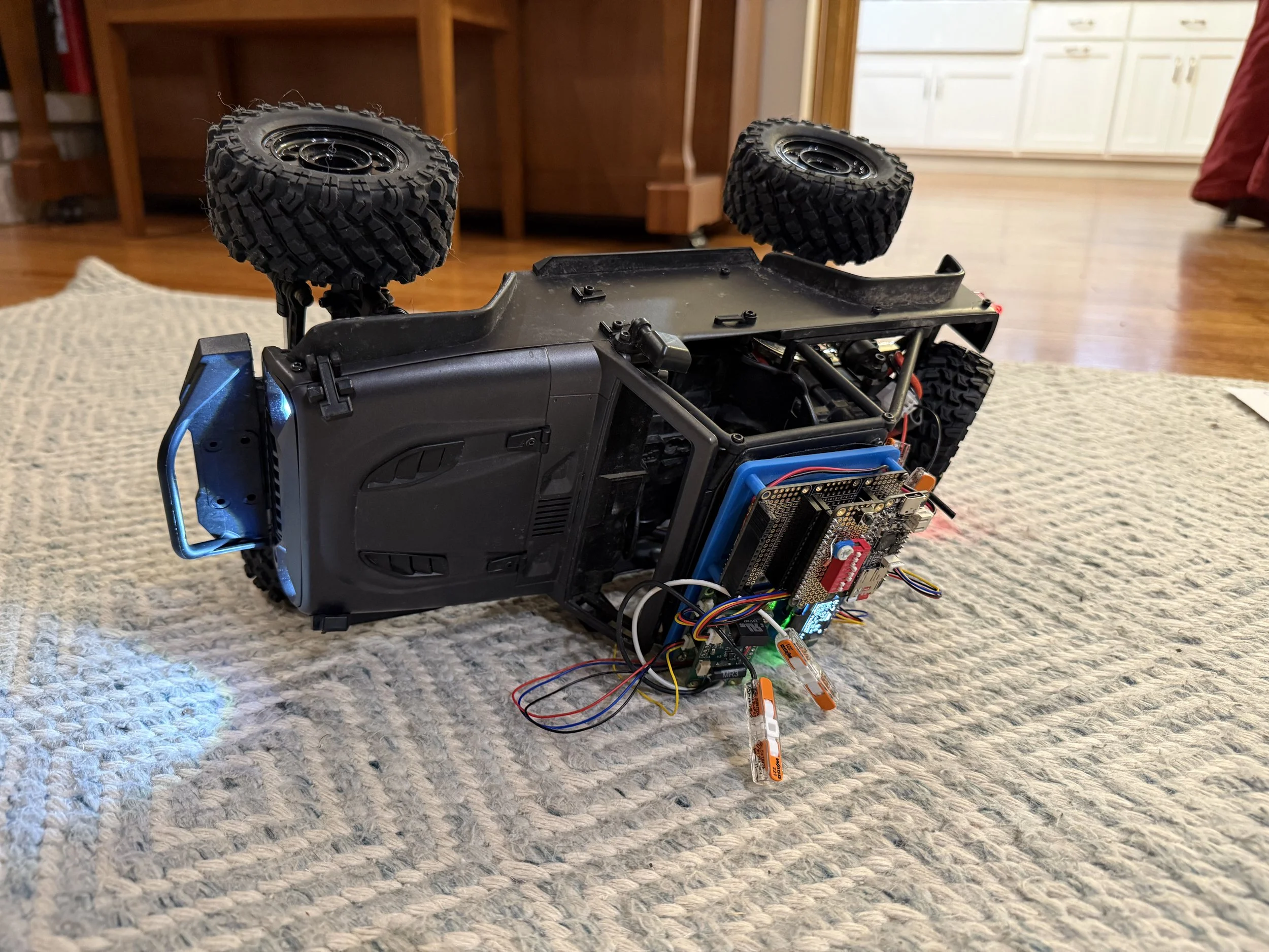
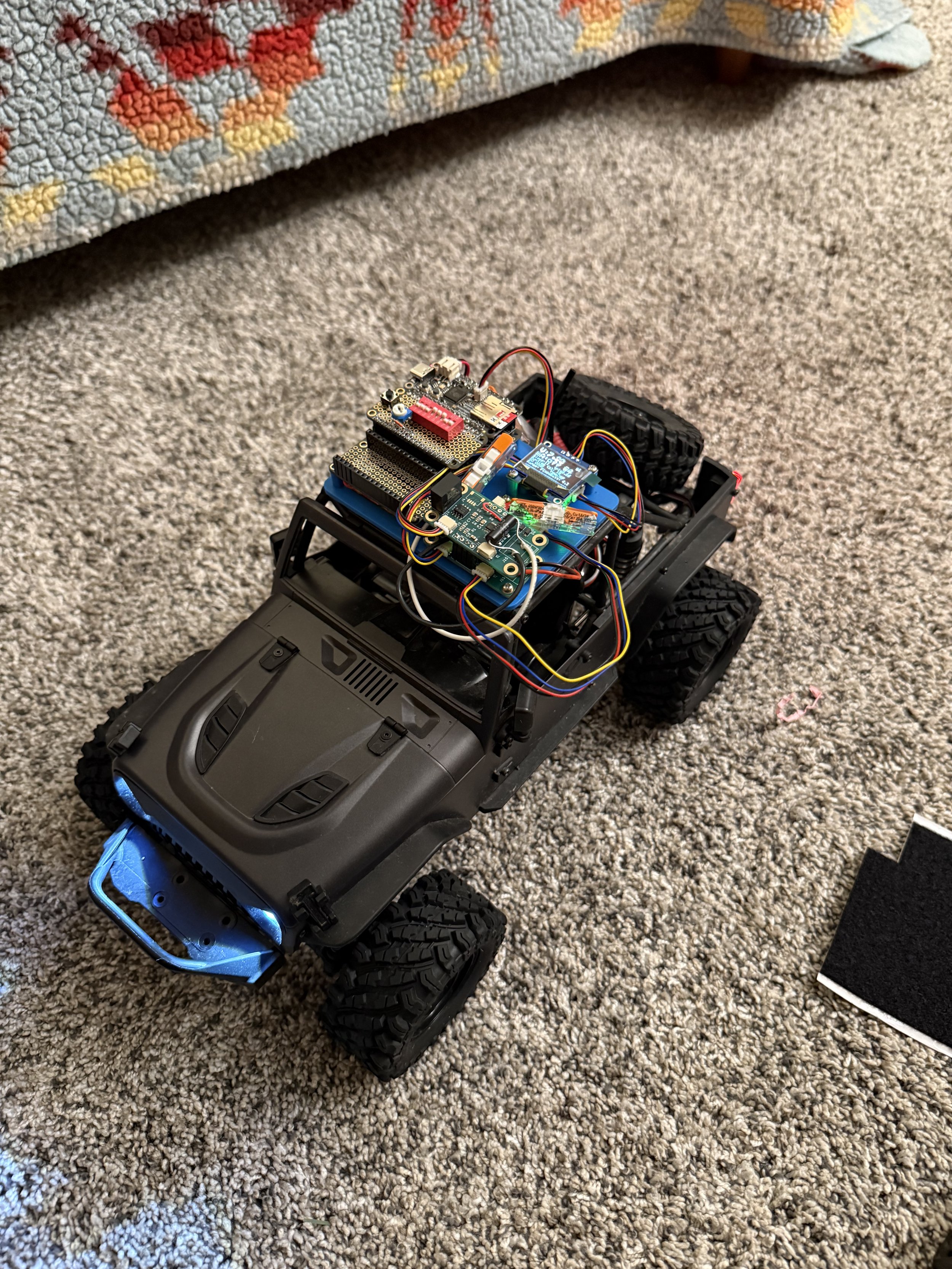
Fortunately, it survived the rollover event.
Build of Materials
*as with everywhere on my website, these are not affiliate links and I make no money if you use them or not.
Here is the BOM:
Adafruit “Adalogger” RP2040 (~$15 as of writing): https://www.adafruit.com/product/5980
Adafruit ADXL343 - Triple-Axis Accelerometer ($6): https://www.adafruit.com/product/4097
Adafruit PCF8523 Real Time Clock ($5): https://www.adafruit.com/product/5189
Adafruit battery
Adafruit Feather Protoboard ($5): https://www.adafruit.com/product/2884
Adafruit FeatherWing Tripler ($9): https://www.adafruit.com/product/3417
(Note: the doubler is out of stock, which is why I used the triple)
Generic 1306 OLED display
Stemma QT - type Cables
Misc: DIP switches, NTC, resistors, button.
2x of my custom isolated ADS1015 boards: https://www.oihdesigns.com/voltmeter-front-end-pcb
MicroSD cards
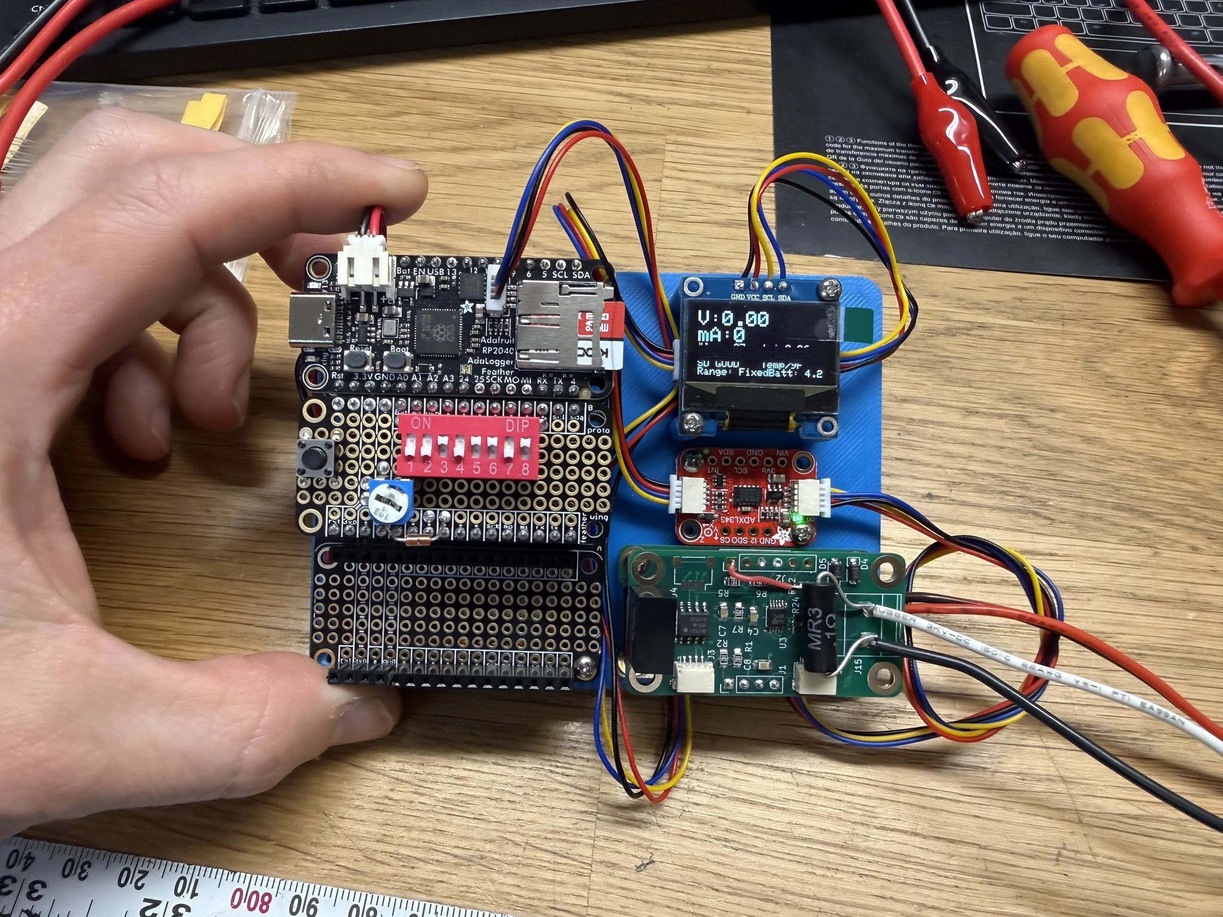
User Controls:
DIP switch:
1: Power Off
This is connected to the enable pin on/off
3: Acceleration Logging Disable
4: Current Logging Disable
5: Voltage Autorange On
By default, the gain on the ADS is fixed for faster logging intervals (you might not want to waste time sending a switch range command when your voltage is spiking). The fixed range has an input max of around +/-60v before saturation at 12 bits (so minimum resolution of ~15mV). With autoranging turned on, the maximum input is +/-90v (~22mV per bit), while the maximum resolution goes down to about 1mV per bit (for inputs less than ~+/-3.8v). The time penalty is ~1-2mS for the range change.
6: Slow Log Interval
By default, the board writes its values to the SDcard every second (unless triggered). This changes the interval to every second.
7: Screen and Serial Updates Disable
8: SD Card Writing Disable
User Button:
This is the “Mark Tape” button. This forces a log and puts “Mark” in the last column
Potentiometer:
This adjusts the trigger threshold for the voltage and acceleration. When acceleration logging is enabled, the voltage default trigger is 0.25v. If acceleration is disabled the voltage interval can be adjusted. If acceleration is re-enabled the voltage threshold stays fixed.
I have plans to make this also adjust the current threshold through a similar mechanism. Haven’t gotten there yet.
I also plan to make the gain for each of the inputs a function of the trigger threshold (i.e. if you trigger threshold for voltage is 3vdc, your input max might be 60v, then 1.5v trigger is 30vdc max, etc). I haven’t had a chance with this either yet. (Edit Draft V2: I asked Claude Code to implement this, and it seems to have, but I need to verify function still).
Coding
The code repository is linked at the top.
Triggering
This is the only not more-or-less trivial part of the code.
The triggering code is optimized to maximize logging frequency when something interesting happens, and minimize writes when nothing interesting happens.
“Something Interesting”
I define this as “a value that is more than X different than the previous logged value,” and always have a starting placeholder value. When this happens, the data is written to an internal buffer. Then a new measurement is taken. If that value is also x different it is also written to the buffer. Otherwise the buffer is written to the microSD card. For example, imagine the voltage is steady at 12vdc with a 0.25v trigger threshold. The value jumps to 12.3v, and that value is written to the buffer. On the next the loop the value is now 12.6, so that is also written to the buffer. On the next loop, the value is 12.65. This is less than the threshold, so the buffer is written to the card. On the next loop (after writing) the value is 12.0, so it is written to the internal buffer. If the value is 12.0 again on the next loop, then the buffer is written to the card.
We do it this because writing data to the SD card is obnoxiously slow (single digit milliseconds), so we don’t want to write while something interesting is happening. This is a reasonably simple way to accomplish this.
Results:
Here is an example of logging sine waves at 1, 10, 100, 1k, and 10kHz:
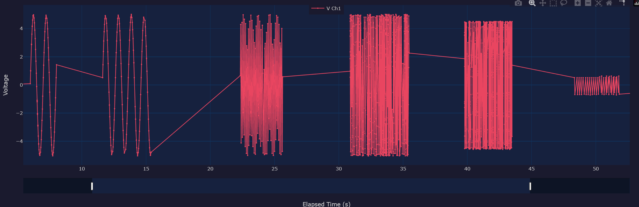
1Hz (first two segments), 10Hz, 100Hz, 1kHz, and 10kHz logging
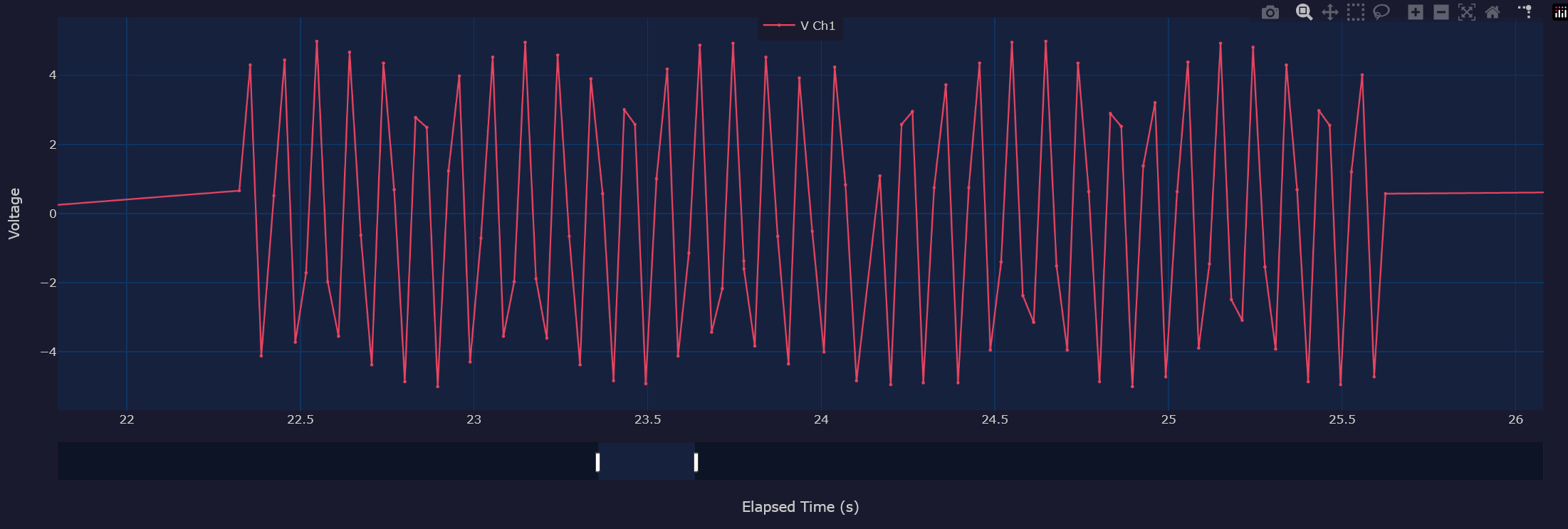
Detail of the 100Hz.
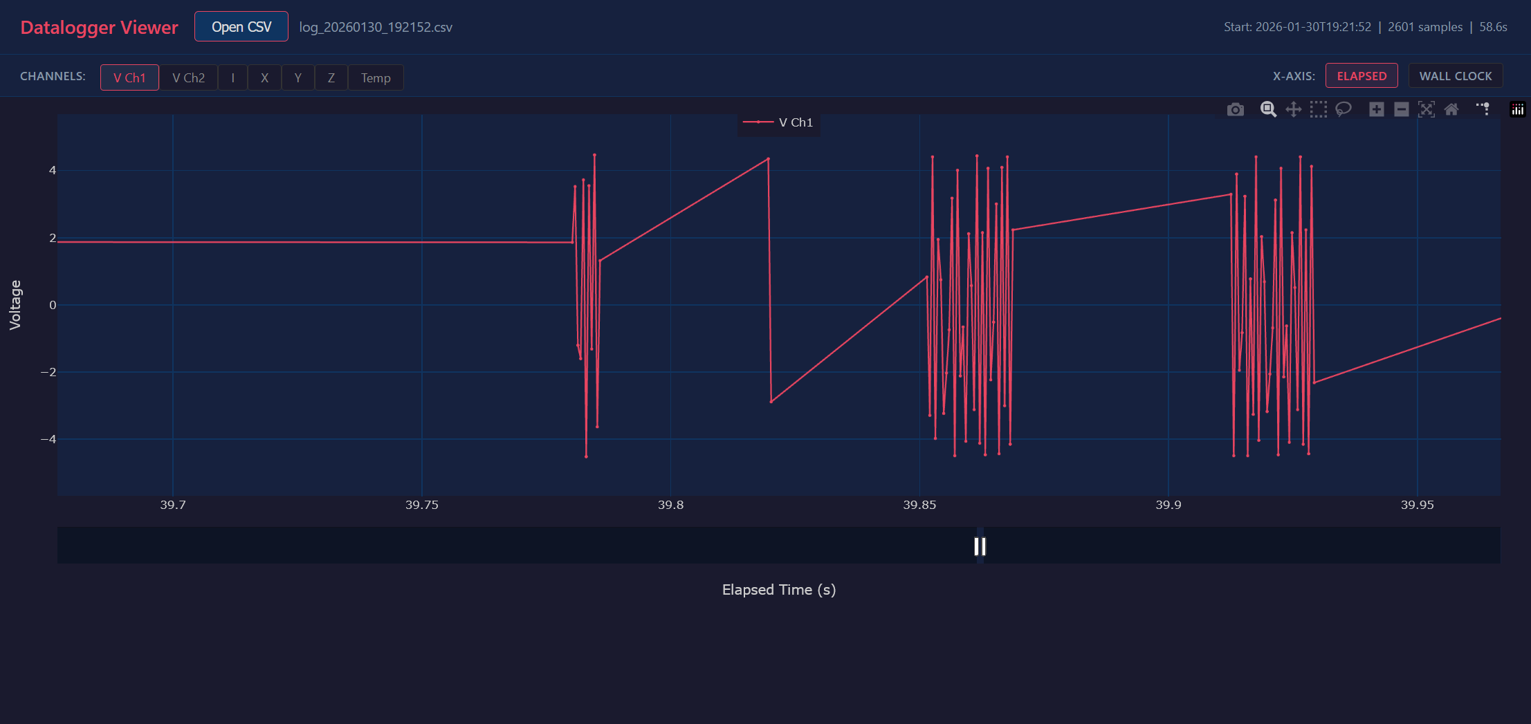
Detail of the 1kHz.
This is with only the voltage turned on, so it’s logging at a max interval of 2kHz. When you look at the data you see many bursts at that rate, until it happens to catch 2 points fairly close to each other, and then there is a ~40mS pause while it writes the data.
Here is the RC car acceleration logging:
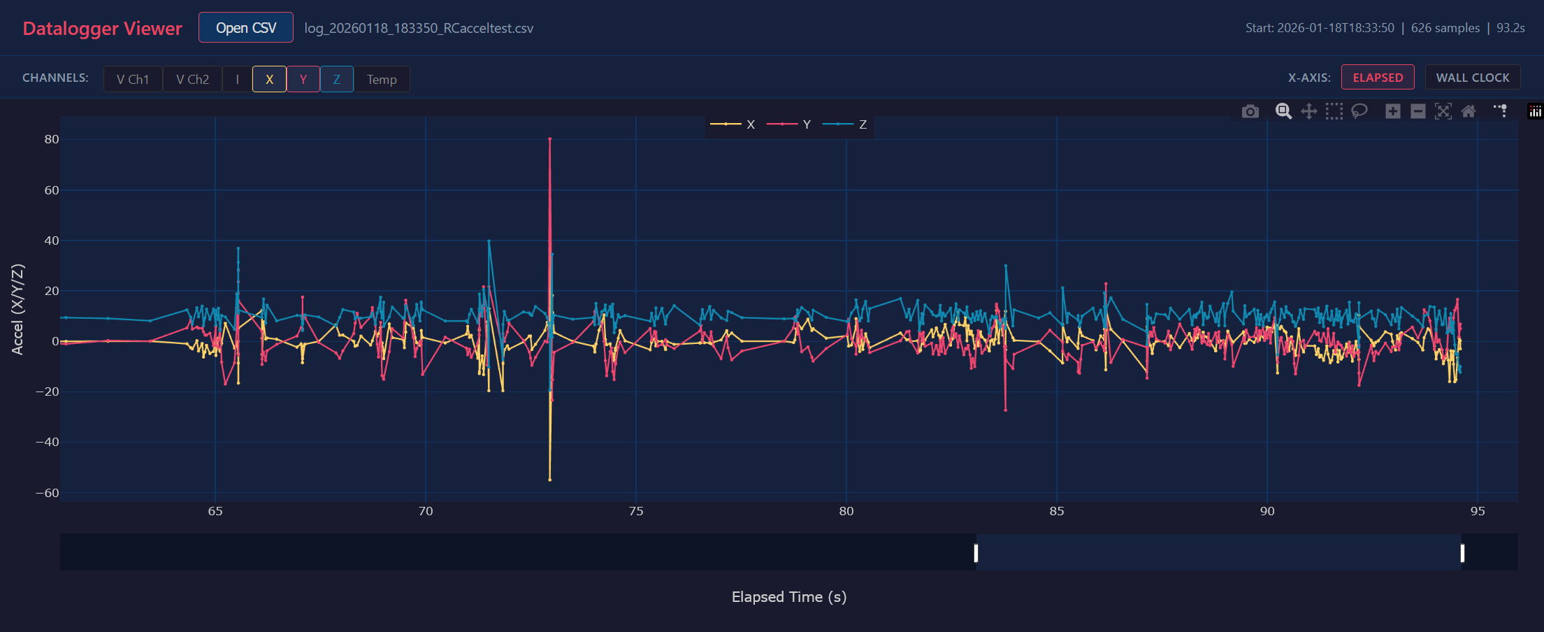
The big spike near second 73 is hitting a wall head on. You can also see at the end that Y and Z transpose, which is where I rolled it (the roll then caused a reset on the board, which is why the data ends there).
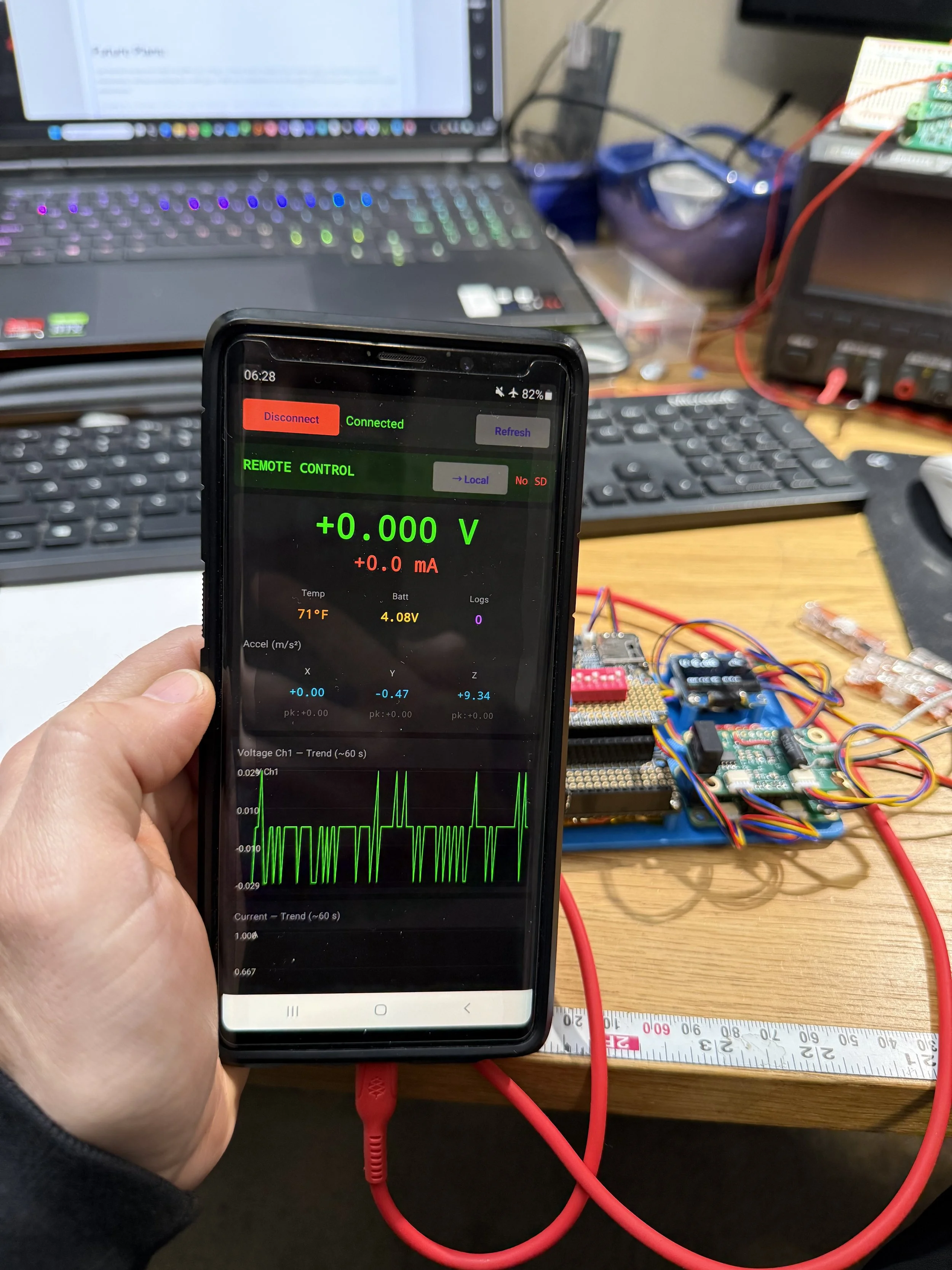
Android App
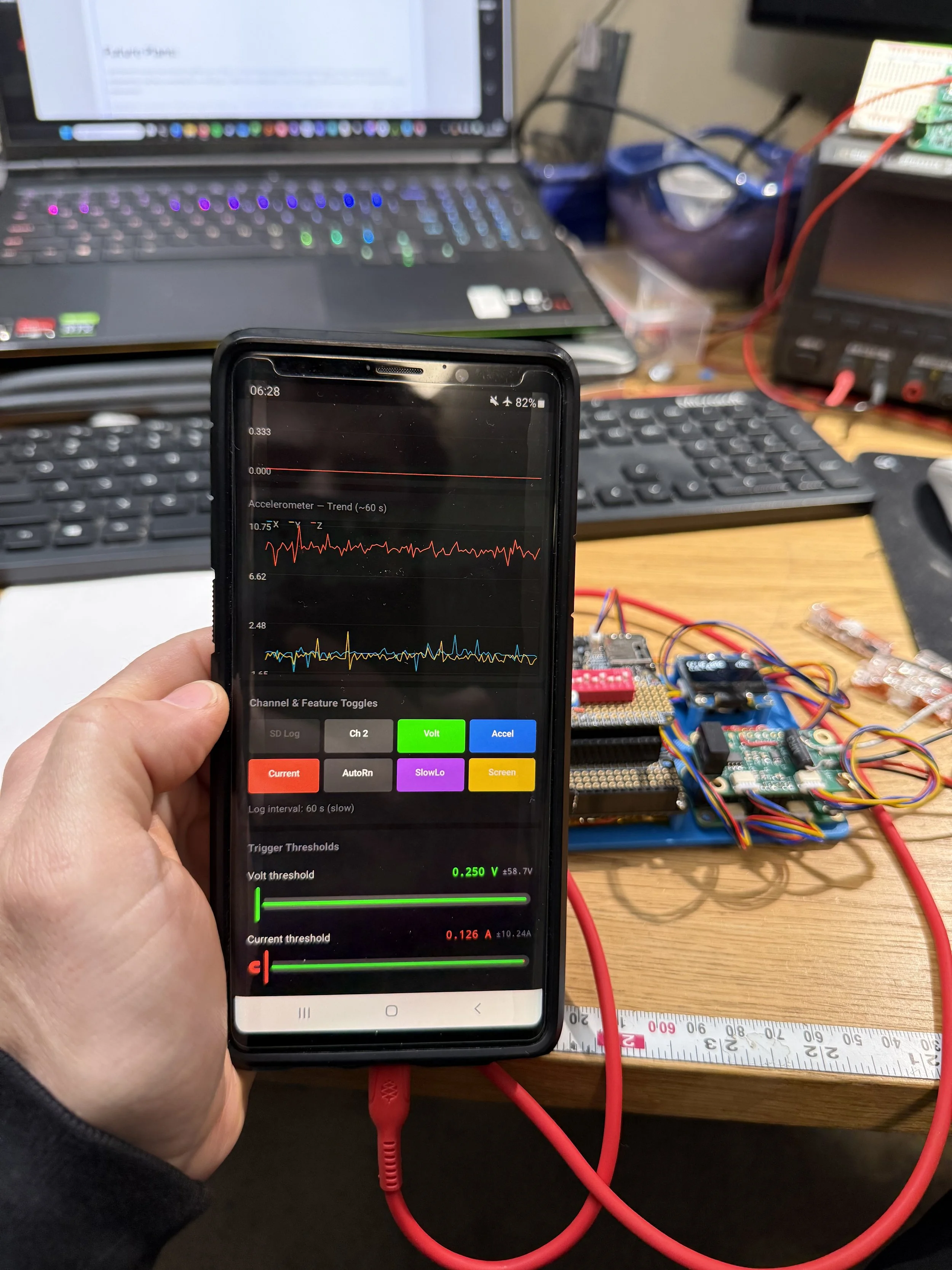
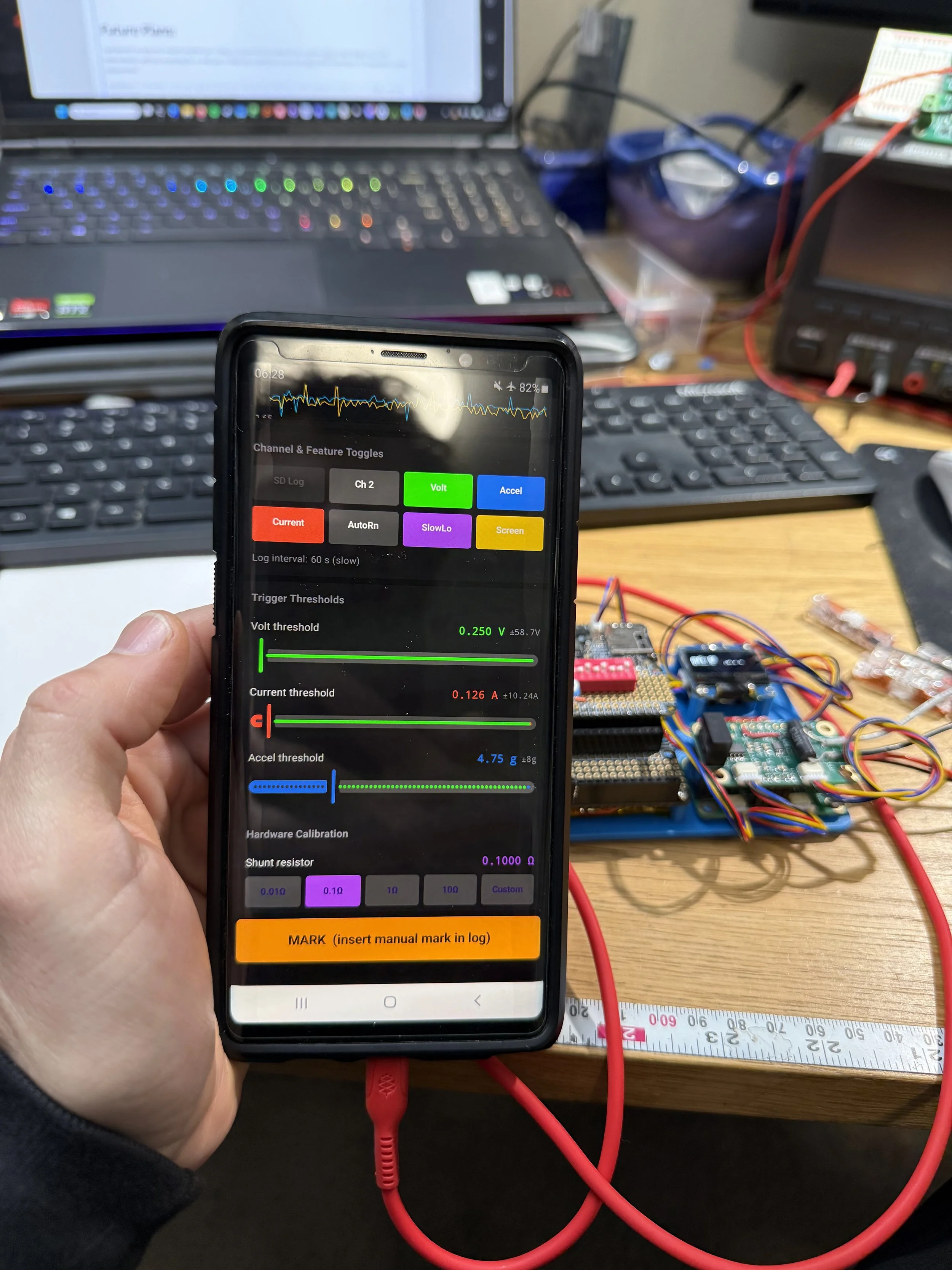
I made an Android app GUI as a proof-of-concept test to see how hard it would be. It is extremely easy:
The process: Take your sketch, give it to Claude Code, ask for an Android GUI, and answer the questions it has. It took less than an hour for me to have a GUI app, although I then wanted various enchantments (like the dynamically updating saturation values based on the trigger values) and that took a little longer.
This app works much better than the awkward set of buttons, switches, and potentiometer for adjusting the settings.
Future Plans:
I just learned recently that isolated amplifiers are a thing. In a future version instead of two separate ADCs to log voltage and current independently I will have something like an AMC3330 or AMC1200 connected to one of the ADC’s differential inputs for independent current measurement.
Including the acceleration on this was a good familiarization exercise, but in the future I think dedicated acceleration and voltage / current logging makes more sense, mostly from a GUI perspective.